

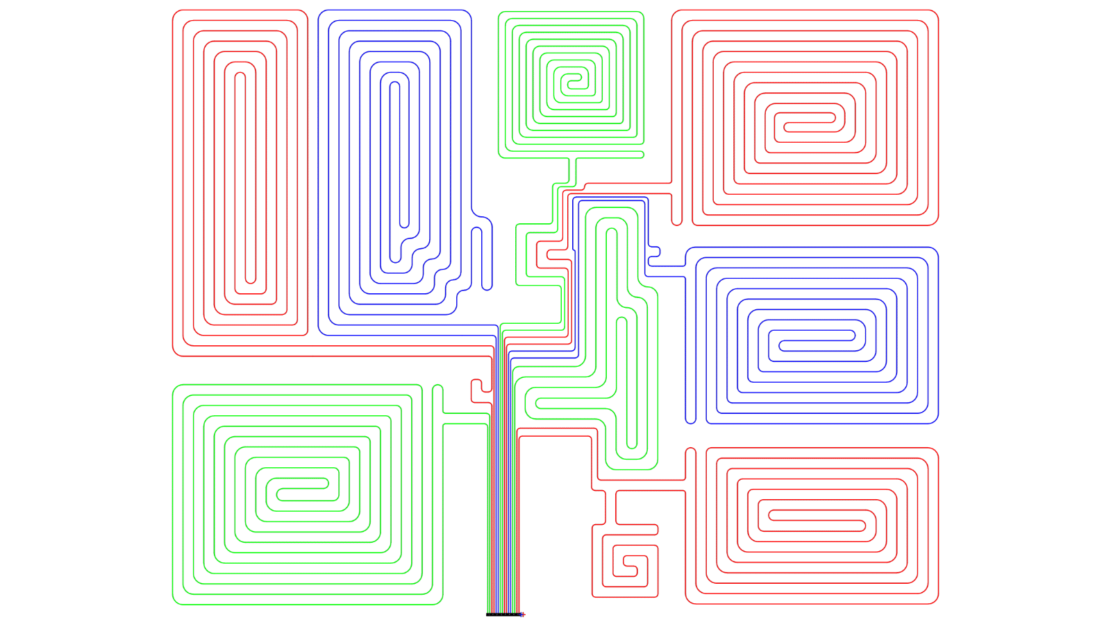
A professional underfloor heating layout must not only be technically accurate; it must also reflect the client’s drawing standards and working methods. Installation companies often have their own conventions for annotations, tables, colours, dimensions and the presentation of technical information.
At UFH Design, part of Fabricon, we adapt underfloor heating layouts to these client-specific requirements. This allows customers to retain their existing CAD standards, even when they outsource underfloor heating engineering.
October 2026 — Part 1 of our article series on client-specific CAD standards.
Why your own CAD standards matter
Within installation companies, technical drawings are used by project engineers, planners, project managers, installers and other stakeholders. Consistent drawing standards ensure that information is presented clearly and remains familiar to everyone involved.
When layouts are prepared by an external engineering partner, it is important to preserve established working methods wherever possible. Consider the structure of title blocks, the information displayed in room labels, how manifolds are presented and the colours used to identify different pipe circuits.
By agreeing these settings in advance, a consistent drawing standard can be established and reused on future projects.
Which elements of an underfloor heating layout can be customised?
We distinguish eight elements that can be tailored individually. Many contain configurable attributes, also known as properties, which can be enabled or disabled depending on the client’s requirements.
1. Title block: project information in your company style
The title block identifies the drawing through its administrative and technical details. Depending on your standards, it can include the project name, project reference, client, drawing number, revision, date, scale and company logo. The graphic layout and positioning can also be aligned with your existing drawing standards.
2. Room labels: display only the information you need
Room labels provide an immediate overview of each room’s technical characteristics. These may include the room number, room name, floor area, pipe spacing (centre-to-centre), heat demand or heat output, and other available design data.
The client decides which information is relevant. Unnecessary properties can be switched off to keep the drawing clear and easy to read.
3. Manifold labels: recognisable information for each manifold
Manifold labels make underfloor heating manifolds easy to identify on the drawing. They can show, for example, the manifold number, location, number of circuits and available technical characteristics. Both the content and presentation are adapted to the client’s information requirements.
4. Manifold schedules: technical data for each circuit
A manifold schedule lists the underfloor heating circuits connected to a manifold. Depending on the available design information, the schedule may include circuit numbers, room names, pipe lengths, flow rates, heat outputs and pressure losses.
As clients do not all use the same schedule format, the required properties and their presentation can be aligned with existing working methods.
5. Room schedules: an overview of room-specific technical data
A room schedule provides an overview of the rooms within a project and their associated data, such as floor areas, heat demand, heat output and circuit allocation. Here too, we agree which information is displayed and how the schedule is structured.
6. Circuit colours: easily recognisable pipework
Colours help distinguish one underfloor heating circuit from another. A client-specific CAD standard can define the colours used, their sequence and how individual pipe circuits are displayed. This allows layouts to follow the colour conventions already in use within the client’s organisation.
7. Pipe-free zones and hotspots: clearly defined hatching
Pipe-free zones and hotspots are often identified on underfloor heating layouts using hatching or other graphic markings. Their appearance can also be tailored to the client’s requirements, including the hatch pattern, scale, angle, colour and visibility of zone boundaries.
8. Dimensions and text styles: fit your CAD environment
In addition to technical annotations, overall drawing presentation is important. We can therefore work with existing dimensioning and text settings, including AutoCAD dimension styles (DIMSTYLE) and text styles (TEXTSTYLE). Examples include fonts, text heights, dimension lines, units, rounding, alignment and annotation scales.
From individual settings to a consistent client standard
The benefits of a client-specific CAD standard become particularly clear on repeat projects. At the start of a collaboration, we identify the client’s technical and graphic requirements. Where an existing CAD standard is available, we use it as our starting point.
We then document the agreed settings as a client standard. This becomes the basis for new layouts, so annotations, colours, schedules and text styles do not have to be defined again for every project. The result is greater consistency, recognisability and more efficient collaboration.
Outsource your layouts without changing your drawing standards
Outsourcing underfloor heating layouts does not mean an installation company has to change the way it works. At UFH Design, we combine technical engineering with a drawing presentation tailored to each client’s requirements.
Whether the project involves a single home, an apartment building or a large residential development, the agreed drawing standard can be applied consistently. Installation companies can therefore add engineering capacity while retaining their established drawing conventions.
This month: your CAD standards in underfloor heating layouts
Throughout October 2026, UFH Design is highlighting how underfloor heating layouts can be fully tailored to a client’s CAD standards.
In this article series, we take a closer look at individual elements. Over the coming weeks, we will cover:
- Annotations and schedules: configurable properties for title blocks, room labels, manifold labels, manifold schedules and room schedules.
- Circuit colours and hatching: how pipe circuits, pipe-free zones and hotspots are represented.
- Dimensions and text styles: client-specific dimensioning, fonts, text heights and annotations.
- A consistent client standard: how we document these settings and apply them on subsequent projects.
Through this series, we aim to demonstrate the flexibility of our engineering approach and show how an existing CAD standard can be integrated into our workflow. Follow our news updates for the more detailed articles.
Your CAD standards as the starting point
Your CAD standards. Our engineering.
Would you like underfloor heating layouts prepared to your own drawing standards? We would be pleased to discuss how your existing annotations, schedule formats, circuit colours, hatching, dimensions and text styles can be incorporated.
Explore our UFH layout service or contact us to discuss the possibilities.